Garrattfan's Modelrailroading Pages
Fairlie Merddin Emrys
6.1 Aprons and tanks
| A few days short of Christmas 2016 I completed the power bogies and so I had my hands free to start work on the superstructure. | |
Aprons
|
|
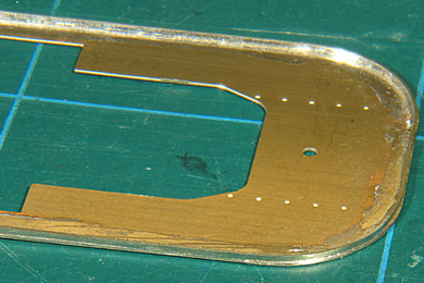
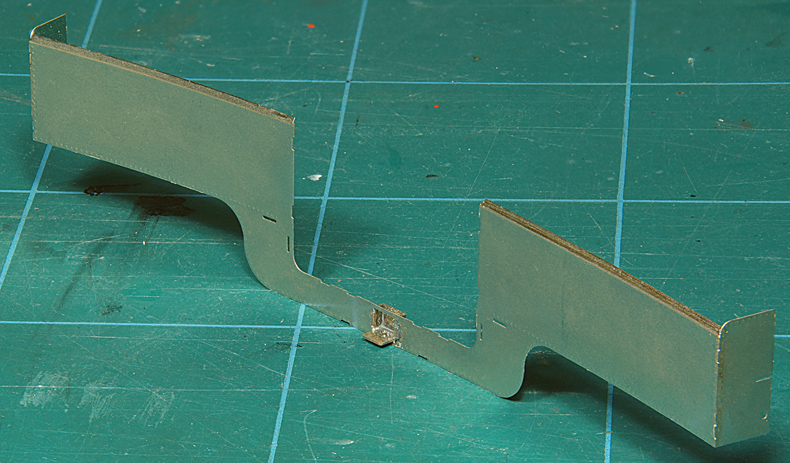
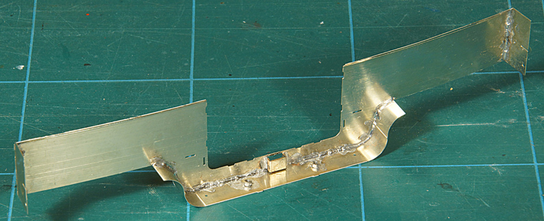
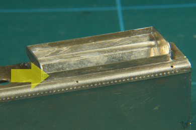
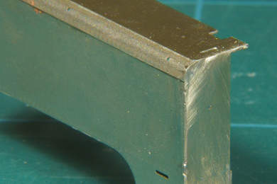
Soldering the valances [1-14] wasn't too much of a pain. Follow the instructions in the manual closely and it will be a doddle. A few additional remarks though.
Normally I clean up the etching cusps before anything else but with the aprons I changed that work order. The thin parts are flimsy so I first soldered the valance which strengthens the apron considerably. Pushing out the rivet detail bends the material of the apron. I have not conceived a method that prevents that. I carefully straightened the apron on a glass plate until it lay dead flat again. Than I soldered the valance in place. Tack solder it at the tabs and when satisfied run short seams of solder between the tabs to avoid the build up of heat. Fill the tabs with solder as per the instructions. Clean up the tabs and only now file away the etching cusps both on the rim of the apron as well as on the valance's underside. Check if the apron is still flat |
|
By the way: riveting |
|
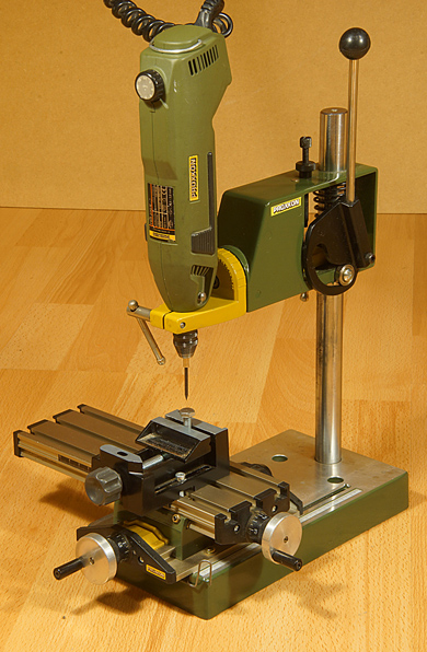 |
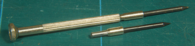
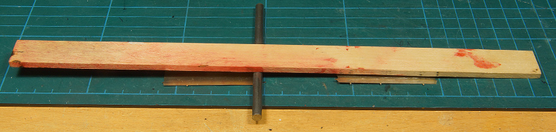
As to the subject of pushing out the rivet detail I had a problem to solve. My rivet pliers went out of business some time ago because the punch broke :-( When I had to press out rivets again when making the aprons I was confronted with the immediate need to have a rivet press. I pushed out the rivets of the first apron using a hand punch that came with a cheap screw driver set. It worked but I kept thinking of a better and more reliable way. It occurred to me that my drill stand with cross table basically had the same functions as an expensive rivet press.
So I cut one hand punch of the two I have to fit in the drill's chuck. I also made an anvil from a stainless steel bolt and tadaaaaahhh I had a working rivet press! See the detail photos on my rivet press page
Preparing the second apron was now great fun! |
Assembly jig |
|
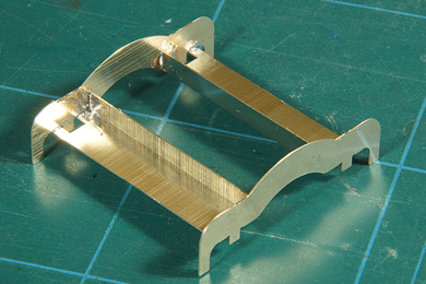 |
The assembly jig was made as per the instructions [16-18]. Nothing much to tell about really ;-) |
Tanks |
|
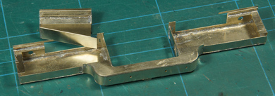
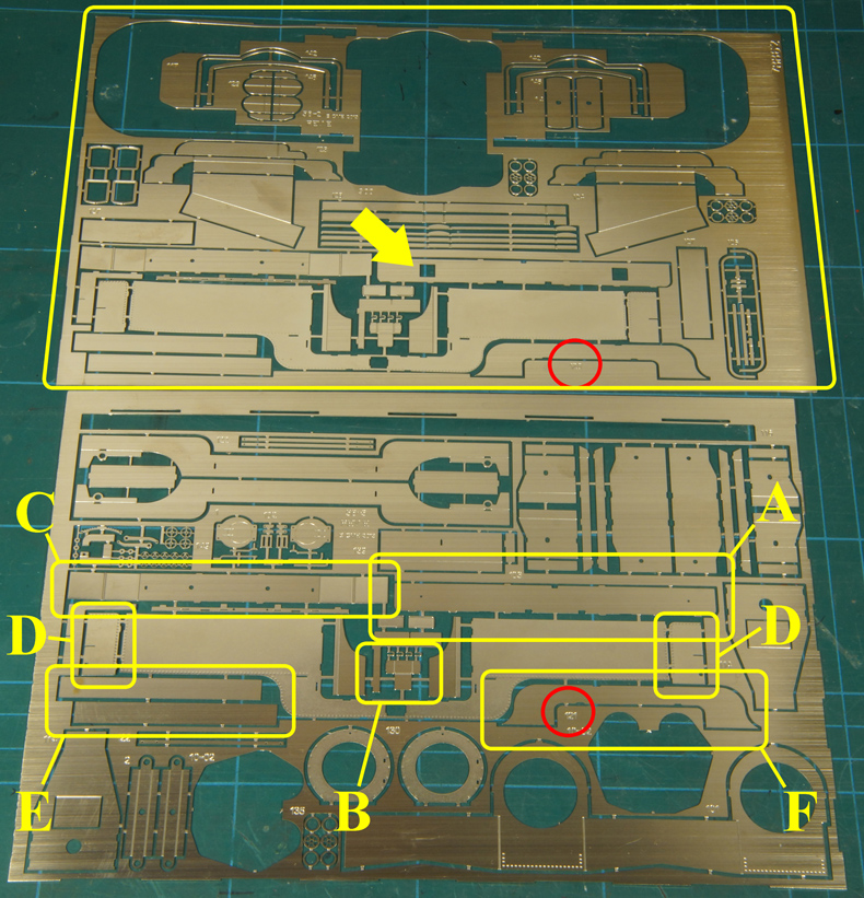
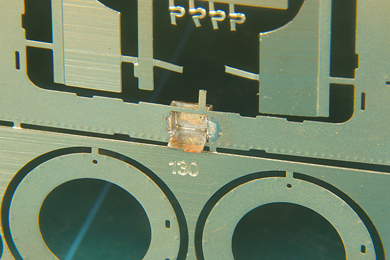
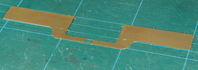
OrientationNow the assembly of the side tanks starts. The manual recommends building the driver's side tank first (instruction [20]) and continues to say that the fireman's side tank (part 120) is identified by the square holes in the centre former [21]. It took me a lot of close observation of text, etches and photos to find out what was meant here.
To save you the work I made a photo of both etches involved. The easiest part of the puzzle is finding the numbers mentioned. 120 fireman's side tank 121 driver's side tank The number are on the etch (red circles) so this gives a quick hint as to which is which, the upper etch contains the fireman's side tank. This is confirmed by the square holes in the centre former. Identifying the centre former was a challenge as it is different on the etch compared to the photos on the DVD. The various parts of the side tanks are not identified individually. The tank sheet itself is identified easily by it distinctive shape. The other parts are as follows A. Centre former (without square holes at the driver's side, compare with the upper etch) B. Centre step C. Centre bottom D. Tank ends E. Parts not mentioned in the manual but in the photos shown as to be soldered in the tank's bottom. F. Side plate (that closes the tank bottom on the inside of the locomotive) Having identified all parts, let's get to work |
|
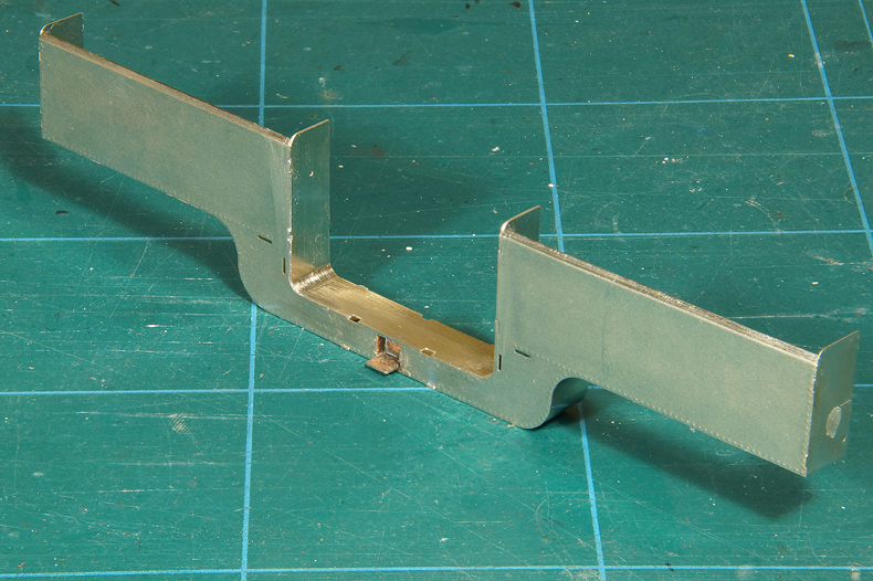
Driver's side tankThe driver's side tank is slightly less complicated because it does not accommodate the coal bunkers. The manual advises to do these first [20]. In practise I found little difference in complexity, but okay, either way is fine. |
|
The centre step (part B) is formed [25] |
and soldered in the side tank while still in the etch [26] |
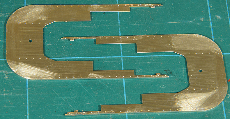
Then the side tank is cautiously cut out of the etch. As always a half etched sheet will tend to curl. Sheet metal is formed by pressing between rollers which exert pressure on the sheet from both sides. The material still contains this strain but as it rolled from two sides this strain is counterbalanced. But if you etch one side away you also remove the counterbalancing half of the strain causing the sheet to curl inwards. The manual does not say anything about this and I expected this curling to be countered during the buildup of the tank. I was wrong! At this stage I should have taken the time to undo the curling by gently coaxing it straight until the sheet would lay dead flat on the sheet of glass. |
|
|
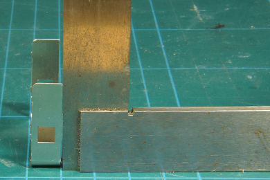
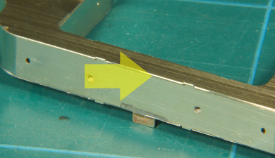
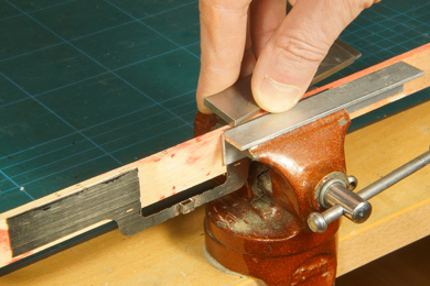
Bending the upper edges [30-32] of the tank proved to be a challenge. Just one millimetre is a very narrow strip to bend at once even when the sheet metal is only 0.3 mm strong. I could not get it round with a steel ruler without exerting excessive force and running the risk that the ruler would slide away and create havoc on the delicate etch. So I used the thick end of my square and ran it along the etch under a slight angle, causing it to bend slightly on the spot where it passed. I ran the square along the edge repeatedly thereby bending it a few degrees more at every pass. Just take care to keep the square at a constant angle. Note that the etch is clamped between two different materials. On the inside there is a piece of aluminium to create enough support. The outside is clamped by a piece of wood to protect the etched rivet detail. |
 |
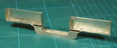
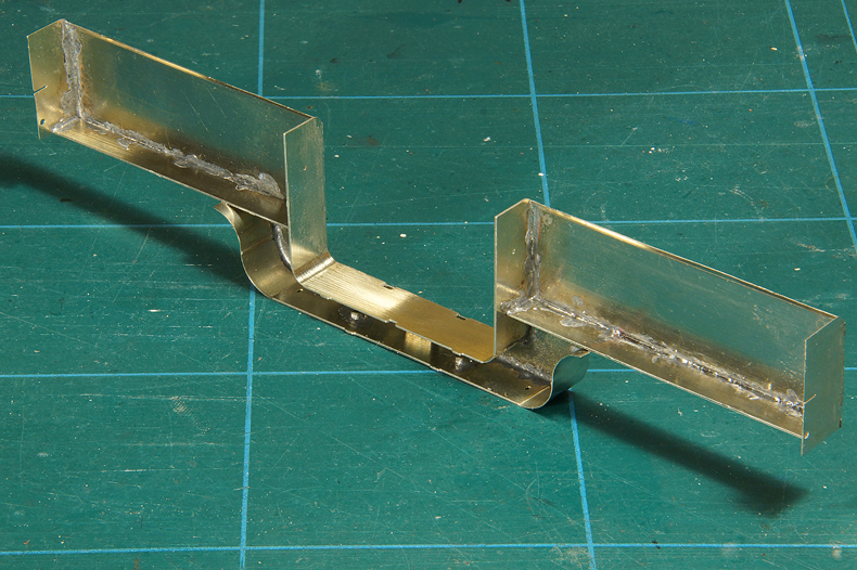
Tank tops bent and tank ends soldered on [33]. As you can see bending the tank tops did little to counter the curling of the sheet metal. |
The centre bottom (part C) was formed and soldered on [35-41]. Heed the advice to tack solder first and then piece by piece fill in the gaps between the tacks. Resist the temptation to run a quick fillet of solder along the seam in one go. Prevent building up of heat or the assembly will distort. You will find by the way that soldering nickel silver is far easier than brass. Brass dissipates the heat much faster, it "sucks" the heat from your soldering iron so to speak. Nickel silver does this less so. The heat stays more local so a quick tack is easier made and the solder flows more easily. You can even hold your work piece with your fingers very close to the tack. Unless you linger with the iron any longer then necessary. Guess why. I forgot to measure the angle of the bottom relative to the tank sides. I assumed it would automatically be 90 degrees, but I was proved wrong as we will see later. |
|
 |
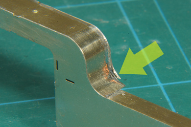
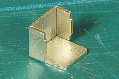
The centre former (part A) was now bent and checked for squareness [42-43]. The one on the photo is for the fireman's side. As said I forgot the check for squareness on the centre bottom but also on centre former of the driver's side and learned the hard way I should have done that. So this photo is to remind you. |
The centre former was soldered in place [44-47]. The sides of the centre former could be soldered from the inside of the tank, but I could not get to the horizontal soldering seam from the inside so I necessarily worked this from the outside.
|
|
Now carefully check if the four tank tops (two tanks ends and two ends of the centre former) line up [48-51]
|
|
Fill in the tank bottoms (part E) again soldering from the inside and tacking first and slowly filling in. Note: the manual does not refer to this step, but the photos clearly have the bottom sheets showing up at this stage (see fig. 22 and 23 on the DVD). The soldering does not look neat but do not fuss about that, it is on the inside! |
|
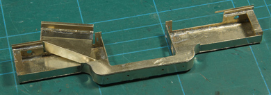
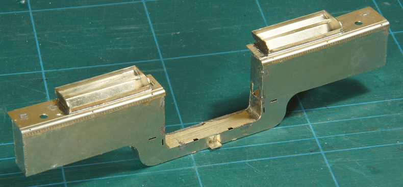
Well, the driver's side tank is slowly coming into existence. Neat job, innit? |
|
 |
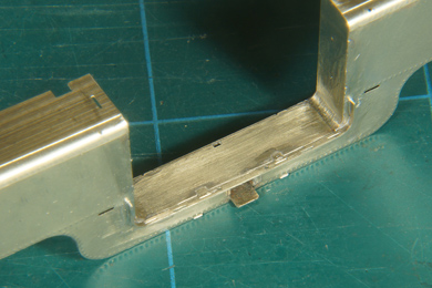
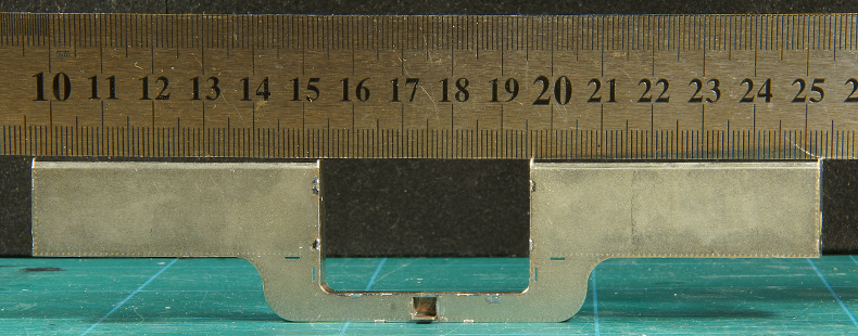
The last plate is fitted now [54]. Ensure before fitting that the whole assembly so far is square and true. Check with the ruler if is straight, both on the bottom end as on the top end. Now is the time to make the last corrections. Once the back plate is soldered on the whole assembly becomes rigid and your options for corrections become very limited. Check, check and check again. Later on the jig will be the harsh judge of your ability to work accurately. |
 |
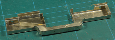
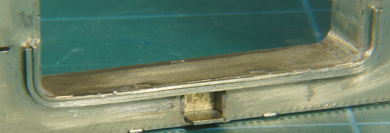
On the driver's side tank, which I assembled first, I had various tell tales that I had not worked up to standard.
First: I found that the back plate would not click into its tabs. The space between the centre bottom and the centre former (top) plate was a few tenths of a millimetre to narrow.
Second: both ends of the back plate protruded from the bottom plate. This kit is very, very accurate, so if you have these issues don't be tempted to think the kit is at fault.
I measured squareness and found the centre bottom plate to be off its required 90 degrees angle. The only explanation for that its that the S-curves were not bent absolutely true over the former. The S then goes out of line. I should have checked that while forming the centre bottom. Its was practically impossible to unsolder the centre bottom without taking the whole assembly apart again. I assessed this error as not overly serious so I decided to leave it and do it better next time. |
 |
|
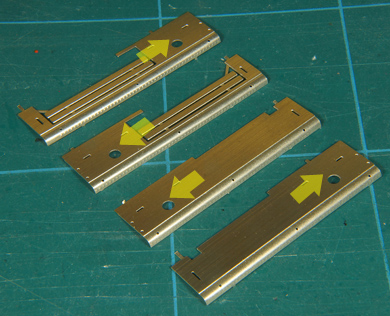 |
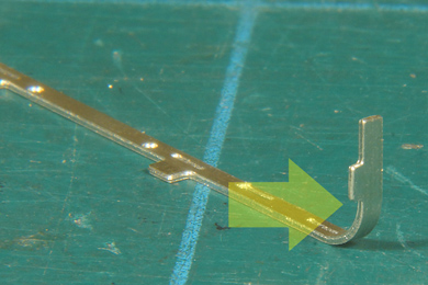
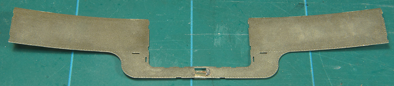
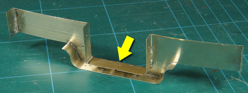
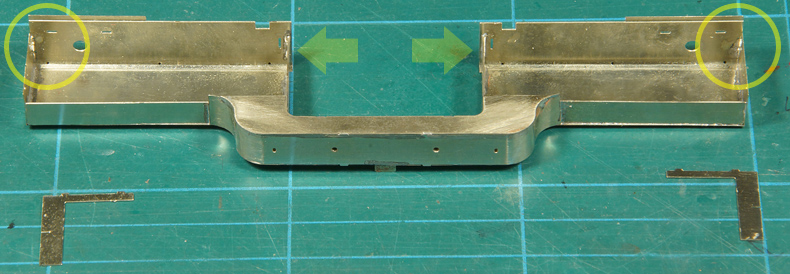
I spent some time searching for the tank tops in the etches until I realised that they were pre-bent and they were in a separate bag. Duhuh. The tank tops come in pairs, one pair for the driver's side (the two at the right hand side) and two for the fireman's side (with the opening for the coal bunker, left hand side). The manual does not mention which end goes where on the tank. So for your reference I added an arrow pointing to the smokebox end.
|
See to it that add the tank tops of the driver's side (no coal bunker hole) actually on the assembly of the driver's side tank (no coal holes), that is what instruction [57] cryptically says. It seems logical but an error is quickly made. The tank tops are slightly oversized. Their position is based on the smokebox end [58]. Ensure a perfect fit there (circles). You will find that the tank tops will overhang the tops of the centre former (arrows). That overhang will be filed away when the assembly has been completed and the entire workpiece is cleaned up. The L-pieces are soldered in place in their corresponding tabs in the tank tops at the smokebox end [60]. |
|
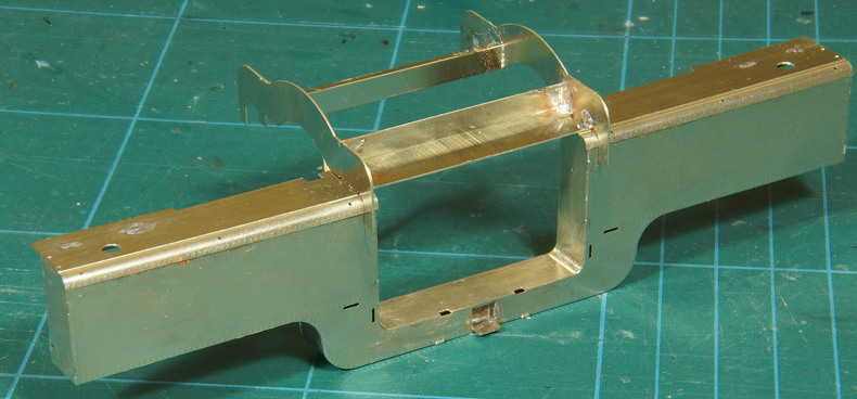
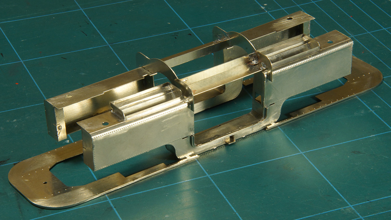
The proof of the pudding is in the eating [63]. Once the tank tops are tacked in place [62] check with the jig if all the work you have done has come together well [63]. There is hardly any play in the jig. It went on the first time so I think I may be content with that (good you can't see my smug face). After this check I soldered the tank tops permanently. |
|
Fireman's side tank.When turning attention to the second (driver's side) tank [67] sheet I did things a little different. As I learned from the first tank side the metal would curl stubbornly and this hindered assembly. So contrary to the instructions I took the tank side out of the etch first and rolled it flat. |
|
|
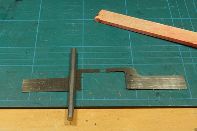
Rolling metal sheet requires some experience but above all patience and caution. It takes three pieces of equipment.
Roll carefully over the plate from left to right v.v. First apply light pressure and see what the effect is. Increase the pressure if you see little effect. Ensure the steel bar runs in a 90 degree angle over the direction of the curl. Also take into account that the narrow parts of the workpiece need far less pressure than the wider parts. Do no overdo it, if it curls the other way you cannot undo it because rolling the other side will destroy the rivet detail. So roll bit by bit and check regularly. It is not difficult, it just take care. |
Mission accomplished: the rolled sheet lies completely flat on the cutting mat. |
|
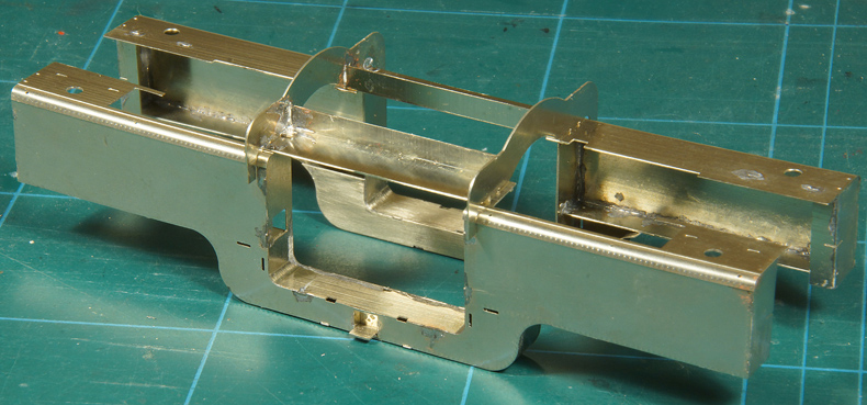
| Before long I had the fireman's side tank ready to the stage of the driver's side and could check that one too [67-68]. Having learned from the first assembly the fireman's side was spot on square and true [69]. | |
 |
|
Coal bunkers |
|
.jpg) |
A few notes on the coal bunkers as the manual isn't too clear about them.
← This is how they sit in the etch.
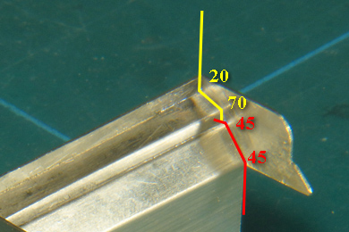
The top end of the bunker two folds. There is one fold visible on the upside of the etch. You will find that there is an extra counterfold line etched on the backside of the etch, very close to the edge (yellow line). This one is folded over at 70 degrees [71]. The other fold, over the etched fold line that is visible on the photo, is bent to 20 degrees in the opposite direction [72], so in the end the bottom narrow strip is in line with the top strip. Then fold the ends (encircled) around [73].
The lower end of the bunker has two folds etched on the backside, both of which are bent to 45 degrees resulting in a 90 degrees position of the top strip relative to the main surface [74].
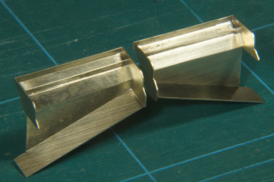
A photo to visualize both parts after finishing and soldering together, just make the angles visible.
|
 |
|
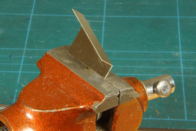 |
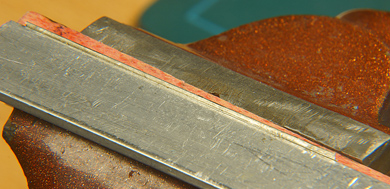
To fold the bottom part I clamped the extremely narrow strips in my vise [74]. It is almost impossible to fold such a small strip in the conventional way. |
 |
Two folds over 45 degrees. The third fold is exactly 90 degrees in the other direction,
The two parts are matched, made to fit and tack soldered. When happy run a seam over it and all is done [74].
Assemble the other tank in the same way [75]. |
 |
The lower part, the coal shute slides just under the top end. Observe the handedness, but it is almost impossible to get that wrong. |
 |
An animation sequence shows how the coal bunker slides in to the tank assembly |
 |
|
 |
|
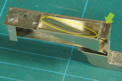 |
It is then soldered in place along the edge from the outside (arrow). A gap remains between the tank side and the coal shute bottom (oval). I wondered if I did something wrong. The photos on the DVD do not show this gap. As I will fill these bunker anyway with coal I decided not to fuss about it. |
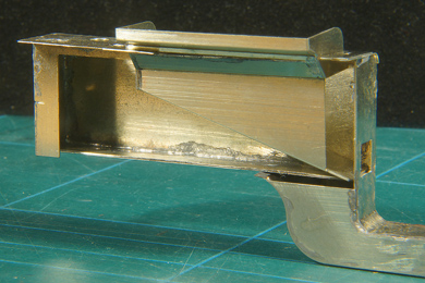 |
The coal shute is also soldered at the very bottom end at the coal hole. |
 |
Finally a strip, contained in the tank top etch, is soldered in the opening of the coal bunker [77] |
Done! |
|
 |
The outside fillets are added [84-87]. The bend that is mentioned is started from the underside of the tab. |
 |
The fillet in place. |
 |
And the valance in place [92]. I forgot to form the fillet taking the valance as a template. I worked on fitting the tabs of the fillet in the slots in the tank side and actually that worked fine. The valance had agood enough fit after some persuasion. |
 |
Now file and sand remaining edges and remove superfluous solder. It took me over an hour, so put on some music and carefully and patiently work your way around the tanks. |
And perform a final check. Don't forget to relish in the very sight of it. After all building is for fun! Although it already gives a good impression of the loco body to be, remember that at this stage the two sides of the locomotive are still separate parts. Joining them is shown on the next page. |
|

Sign my
GuestBook